13 July 2018
My Vivitar 19/3.8 lens took a tumble and the focuser got jammed. I had to disassemble it to fix the problem. Here is a description of the disassembly, down to the main barrel and aperture mechanism, and reassembly.

Vivitar 19/3.8 FD
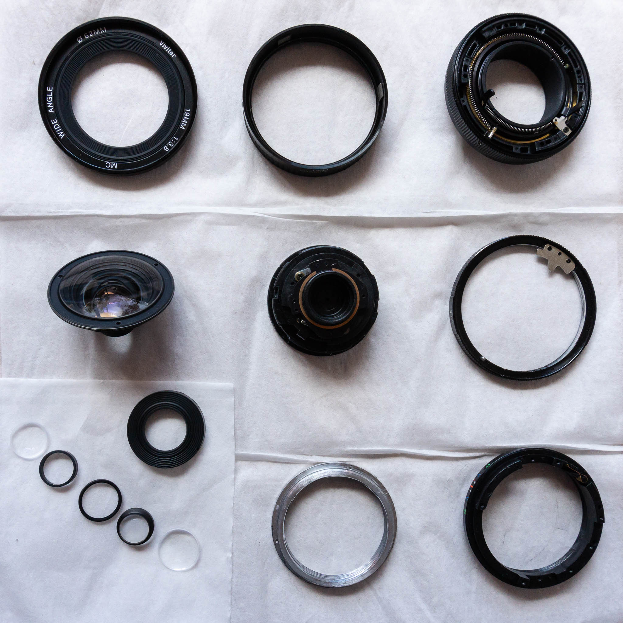
After disassembly. Top row, left to right: filter ring, focusing ring, and mount assembly. Middle row, left to right: front lens block, main barrel, and aperture ring. Bottom row, left to right: rear optics and rear retaining ring, focusing collar, and main ring.
My lens is FD mount, but Vivitar produced this lens other mounts. I expect that disassembly of other variants will be similar, except of course for the details of the mount assembly and its coupling.
If you have comments or additional information on this lens, please get in touch.
Tools
You will need the following tools:
- #00 Phillips screwdriver
- Needle-nosed pliers or industrial tweezers
- 1.4 mm (or similar) flat-bladed screwdriver
- Optional: Ajustable lens wrench to remove the rear lenses without having to remove the mount assembly.
I also recommend:
- Using a container to hold screws and other small parts.
- Wearing unpowdered latex or nitrile rubber gloves to protect the optics, and changing them if they become contaminated by grease.
- Working on a couple of large lint-free tissues to protect the optics.
Disassembly
I’m going to split disassembly into two parts: the front and the rear. In both cases, the disassembly will proceed to what I call the main barrel, which holds the aperture mechanism. I haven’t disassembled further.
Front Disassembly
The filter ring is held in place by friction against the three screws that hold the front lens block in place. This isn’t a great design. You can normally unscrew the filter ring by simply twisting it with respect to the lens body.

The filter ring at the front of the lens

After removing the filter ring.

The front of the filter ring.

The rear of the filter ring. You can see the marks on the bottom of the ring left by the contact with the three screws that hold the front lens block in place.
Removing the filter ring exposes three screws around the front lens. Remove these, and you can lift out the front lens block.
As far as I can tell, the front lens block is a sealed unit.

After removing the three screws that secure the front lens block.

Removing the front lens block.

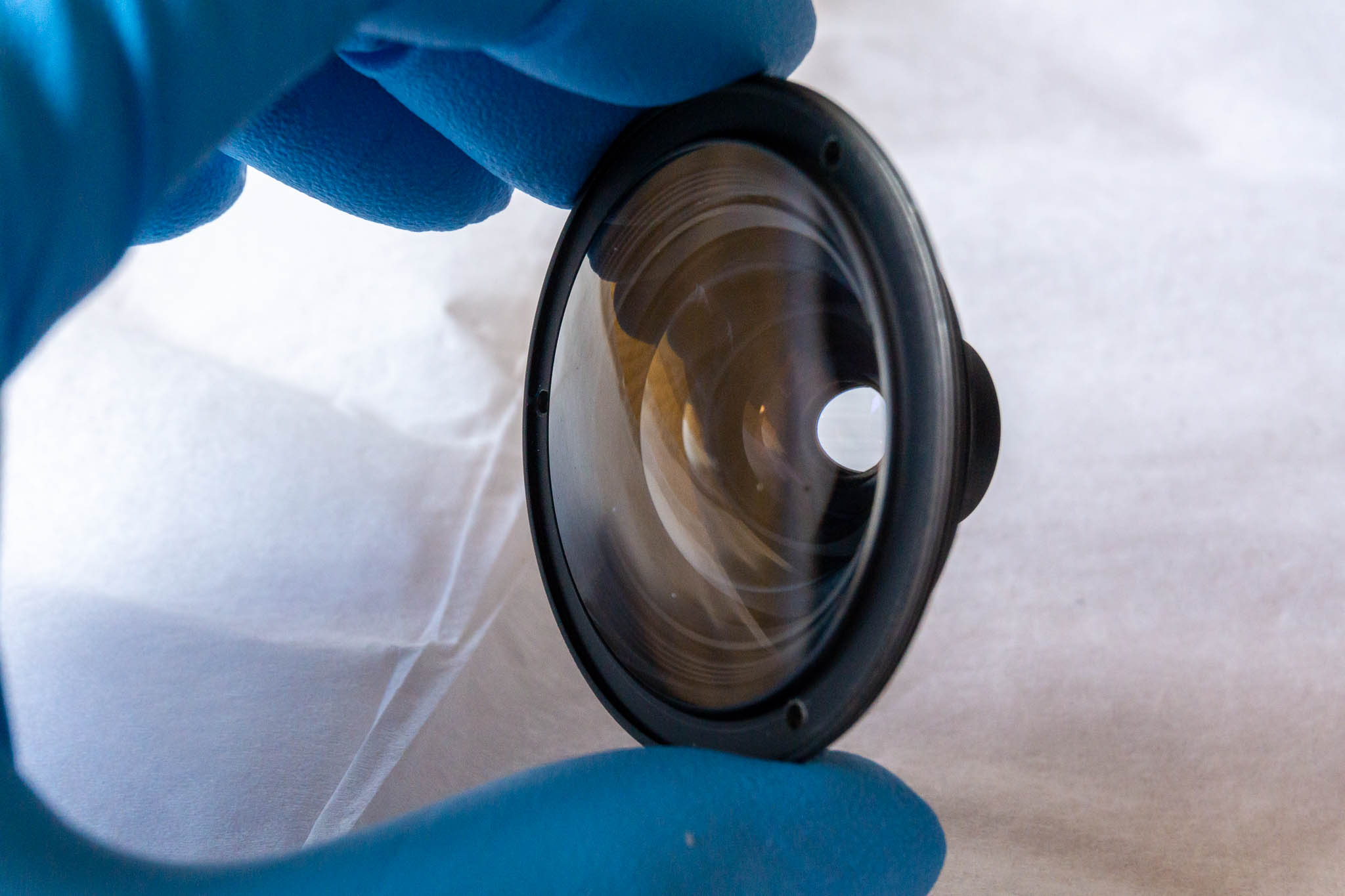
The front lens block.

The front lens block.
You now have access to the front of the aperture mechanism at the bottom of the pit for the front lens block. There are three screws that appear to hold the aperture in place, but I have not removed them.

The front of the aperture mechanism.
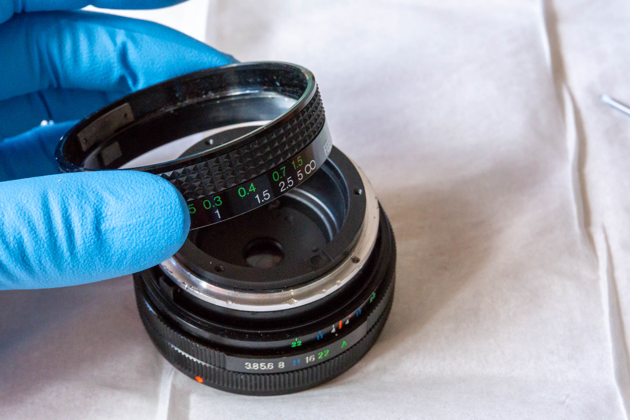
The focusing ring is attached to the focusing collar by three screws. Remove these, and you can lift out the focusing ring.

The three screws that secure the focusing ring to the focusing collar.

After removing the three screws.

Removing the focusing ring.
The focusing ring has two hard stops. They appear to be adjustable, with access to the adjustment screws under the rubber grip on the focusing ring, but I have not confirmed this.

The focusing ring showing the two adjustable hard stops.
This is as far as I’ve gone from the front. We now turn our attention to the rear of the lens.

The main body of the lens after removing the focusing ring.


Rear Disassembly
WARNING: Once you remove the rear retaining ring, the rear lenses are loose. Make sure you take them out in a controlled manner and remember the order and orientation in which they need to be replaced. I recommend laying them out on a lint-free tissue in the order and orientation in which you removed them and taking a detailed photograph.
WARNING: The aperture detent mechanism has a spring that pushes a small ball bearing against the aperture ring. If you’re not careful, when you remove the aperture ring, this ball bearing can go flying and be lost.
If you have an adjustable lens wrench, you can unscrew the rear retaining ring directly using the two slots on its outside circumference without removing the mount assembly. I don’t, so I begin by removing the mount assembly.
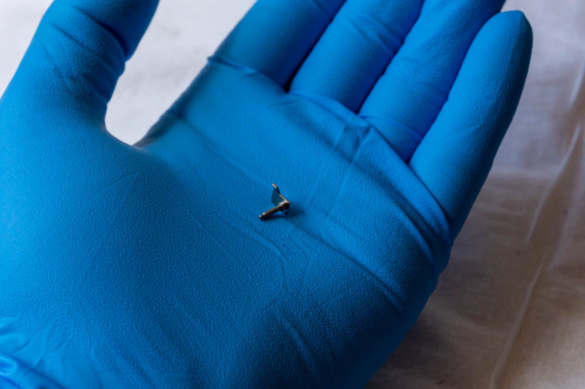
The mount assembly is fixed to the main ring by four axial screws underneath the mounting ring. Once these are removed, the mount assembly can be separated from the rest of the lens. It’s best to do this with the rear of the lens down, so that the AE switch pin does not fall out. You can then remove the AE switch pin with pliers or tweezers and put it to one side.
WARNING: Be careful not to remove the aperture ring just yet, as you can lose the ball bearing that is part of the detent mechanism.

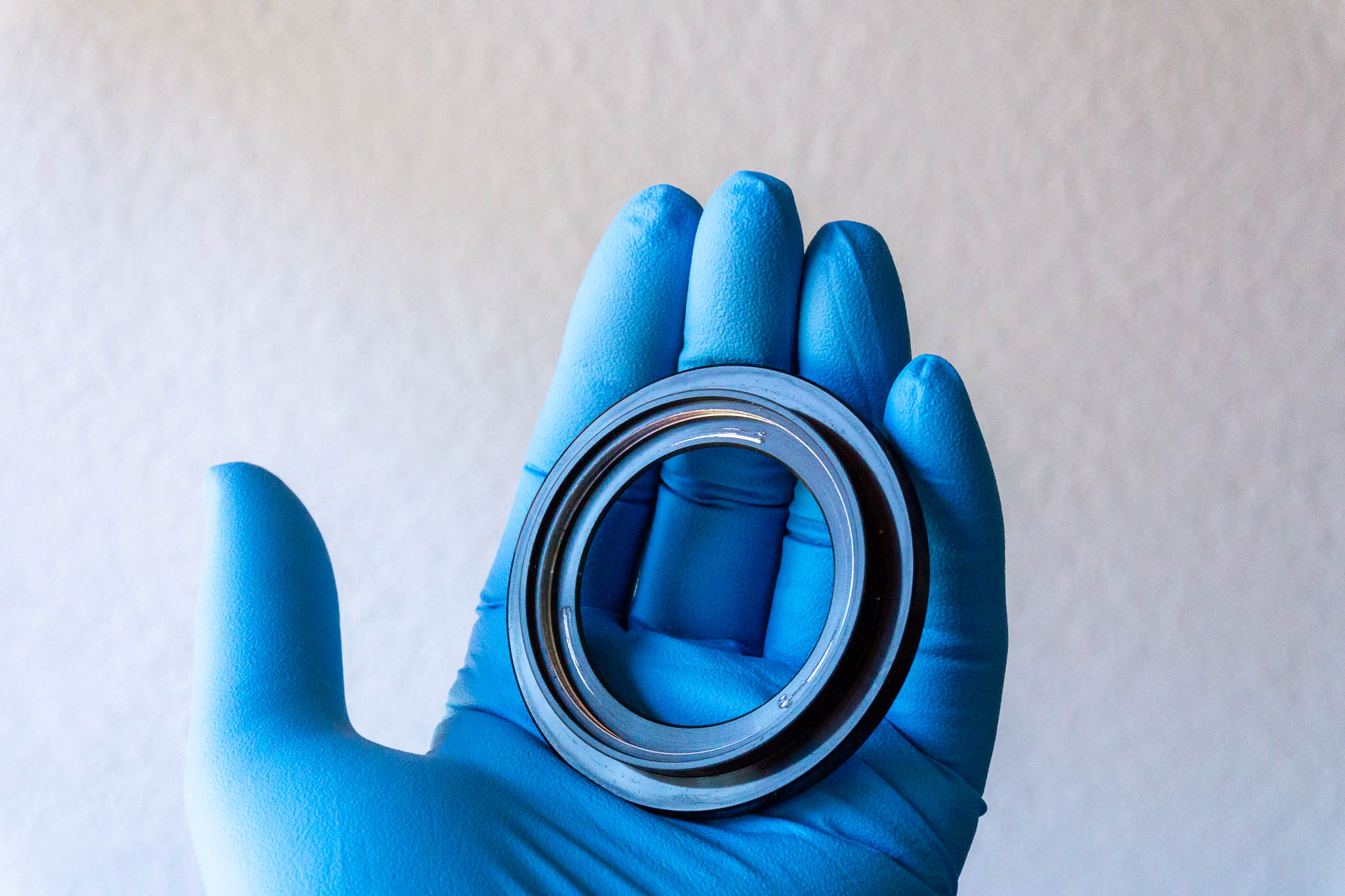
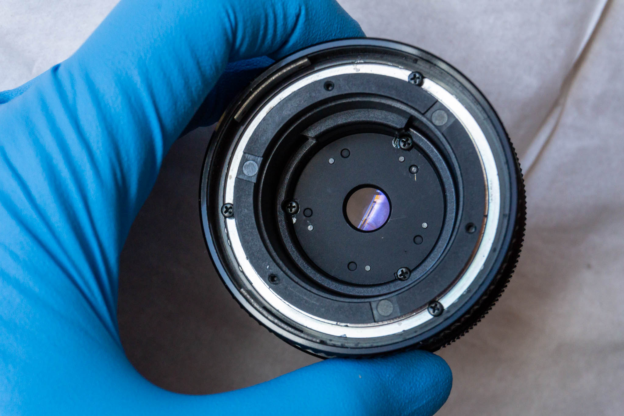
The rear lenses, surrounded by the rear retaining ring (with circular grooves), which is in turn surrounded by the mount assembly.

After removing the four screws that hold the mount assembly to the main ring, you can remove the mount assembly. It’s best to do this with the rear of the lens down, so that the AE switch pin does not fall out.

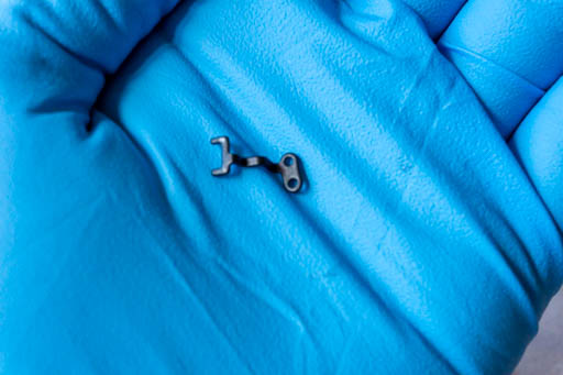
The mount assembly. The AE switch pin is at 11 o’clock.

The AE switch pin.

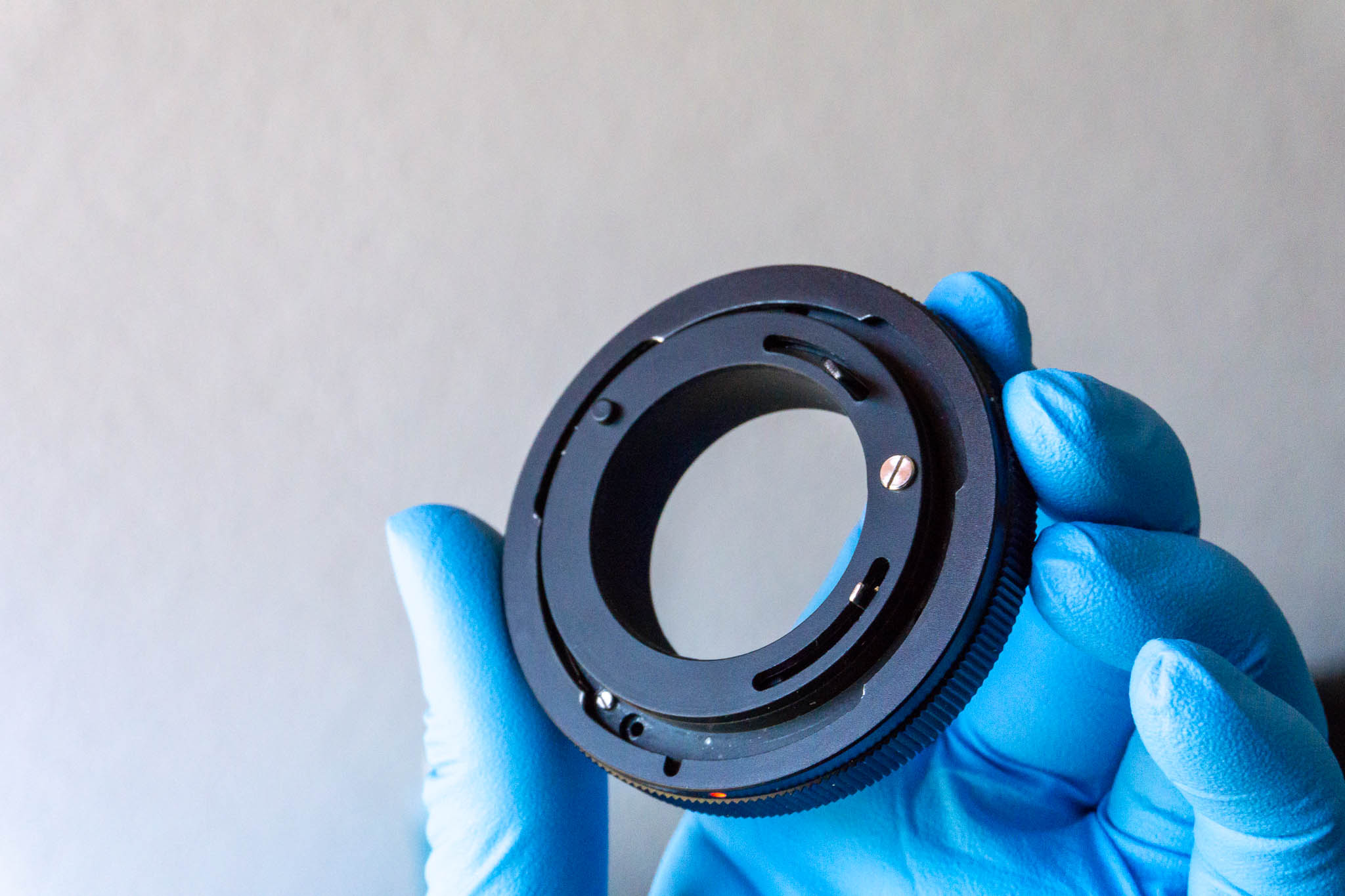
The front of mount assembly after removing the AE switch pin.

The rear of the mount assembly.
The rear retaining ring can now be simply unscrewed with your fingers.
WARNING: Once you remove the rear retaining ring, the rear lenses are loose, so be careful and keep the front of the lens down.
WARNING: Be careful not to remove the aperture ring just yet, as you can lose the ball bearing that is part of the detent mechanism.

The rear of the lens with the mount assembly removed.

Removing the rear retaining ring.

After removing the rear retaining ring.

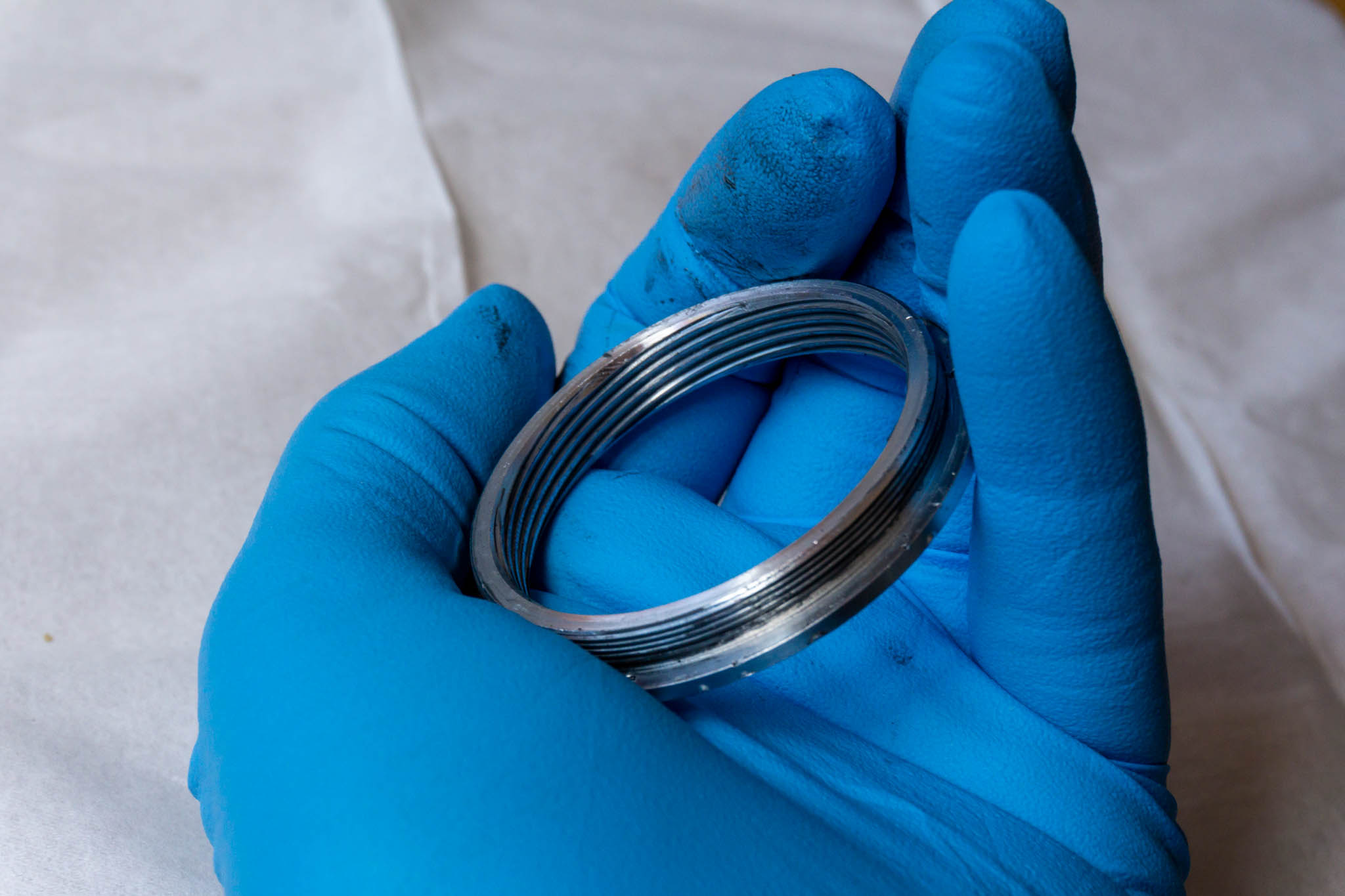
The rear retaining ring.

The rear retaining ring.
You can then gently tip the rear lenses out into your hand. Use a finger to stop them falling. There are five pieces: a rear lens, a rear spacer ring, a middle lens block, a front spacer ring, and a front lens.
WARNING: The spacers have specific front-back orientations, so make sure you remember these. The lenses have their convex surfaces towards the rear.
WARNING: Be careful not to remove the aperture ring just yet, as you can lose the ball bearing that is part of the detent mechanism.

The rear lenses. The rear-most lens is at the bottom.
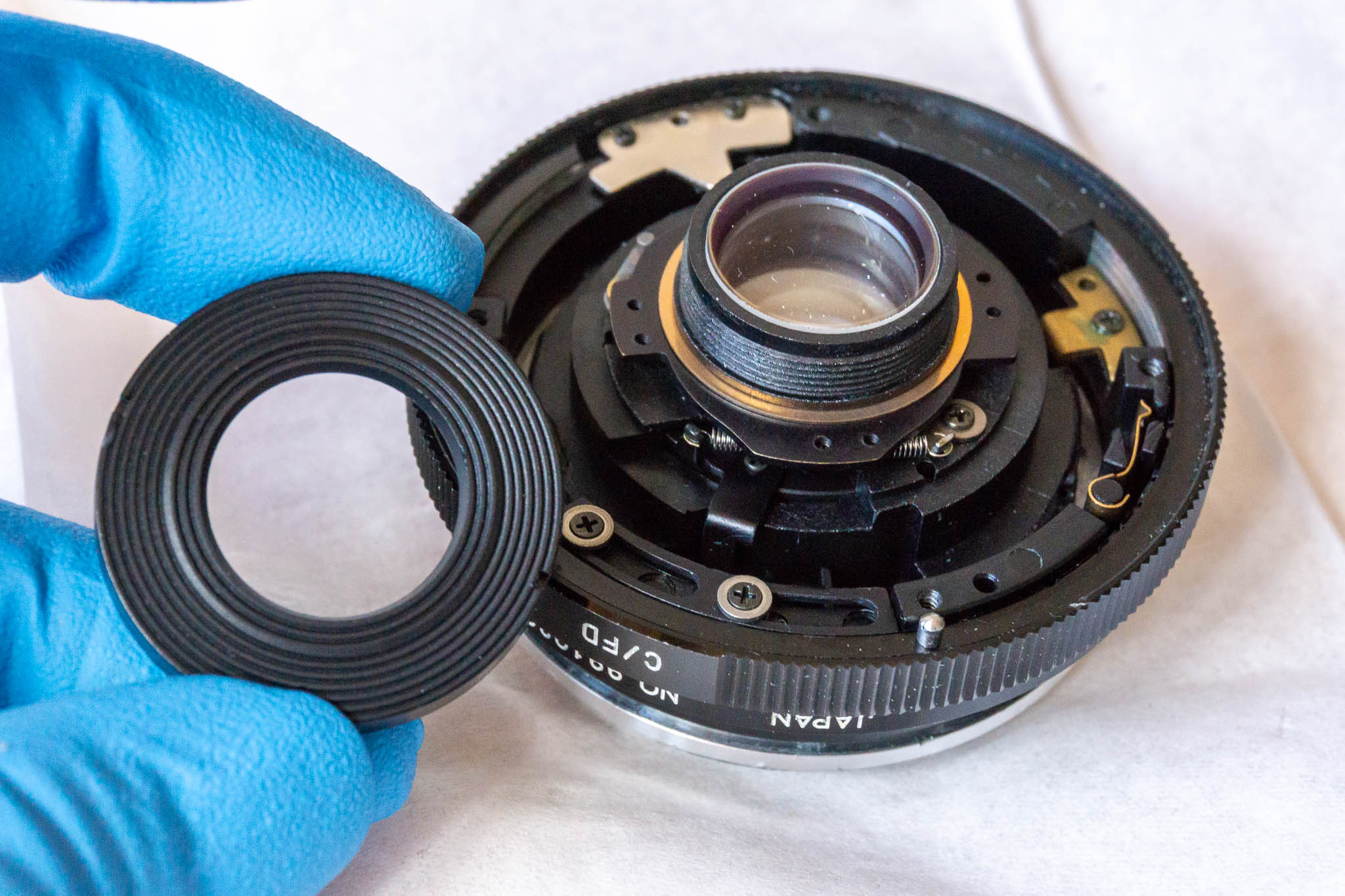
You can now lift out the aperture ring. The detent mechanism has a spring that pushes a small ball bearing against the ring. If you’re not careful when you remove the aperture ring, this ball bearing can go flying and be lost.

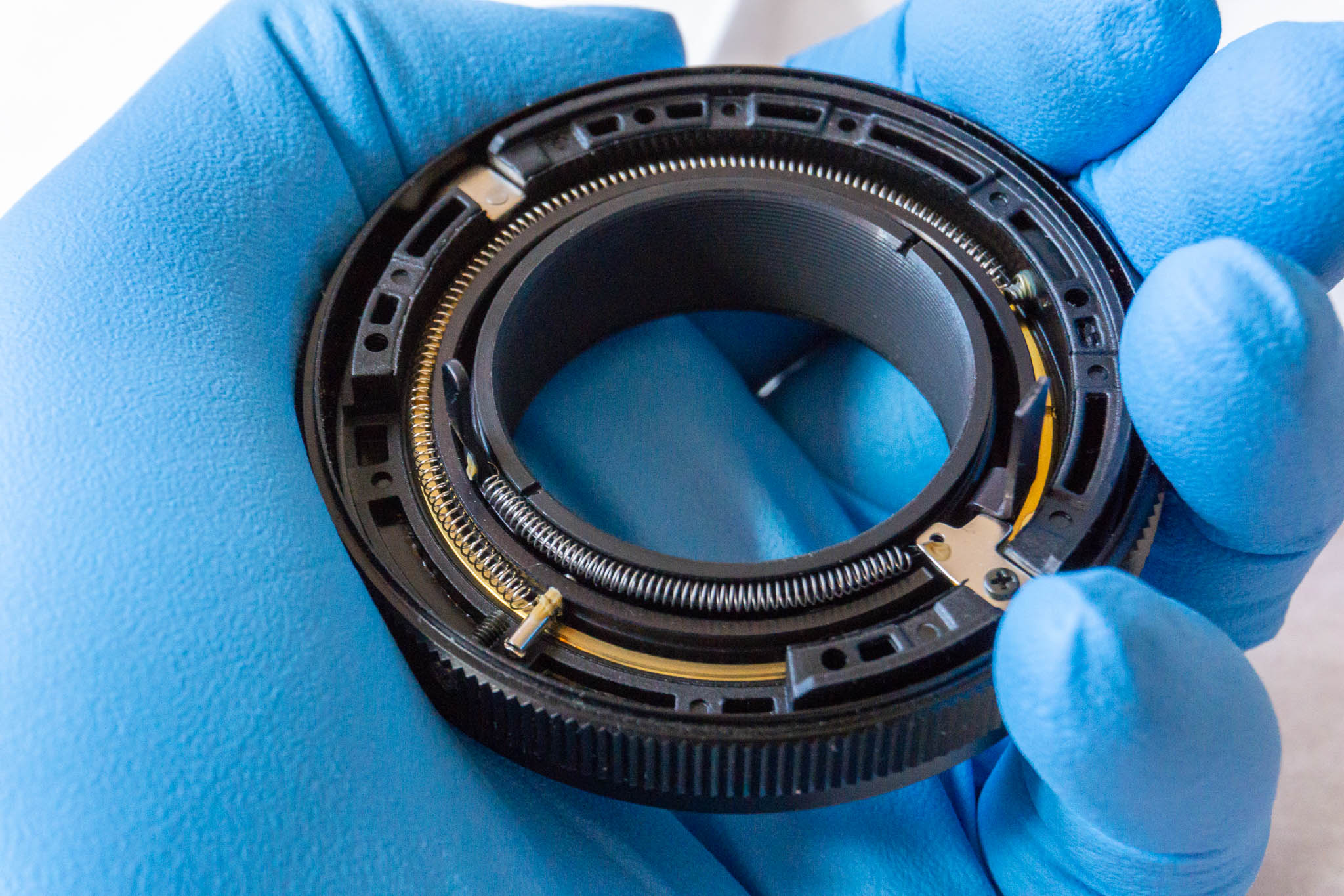
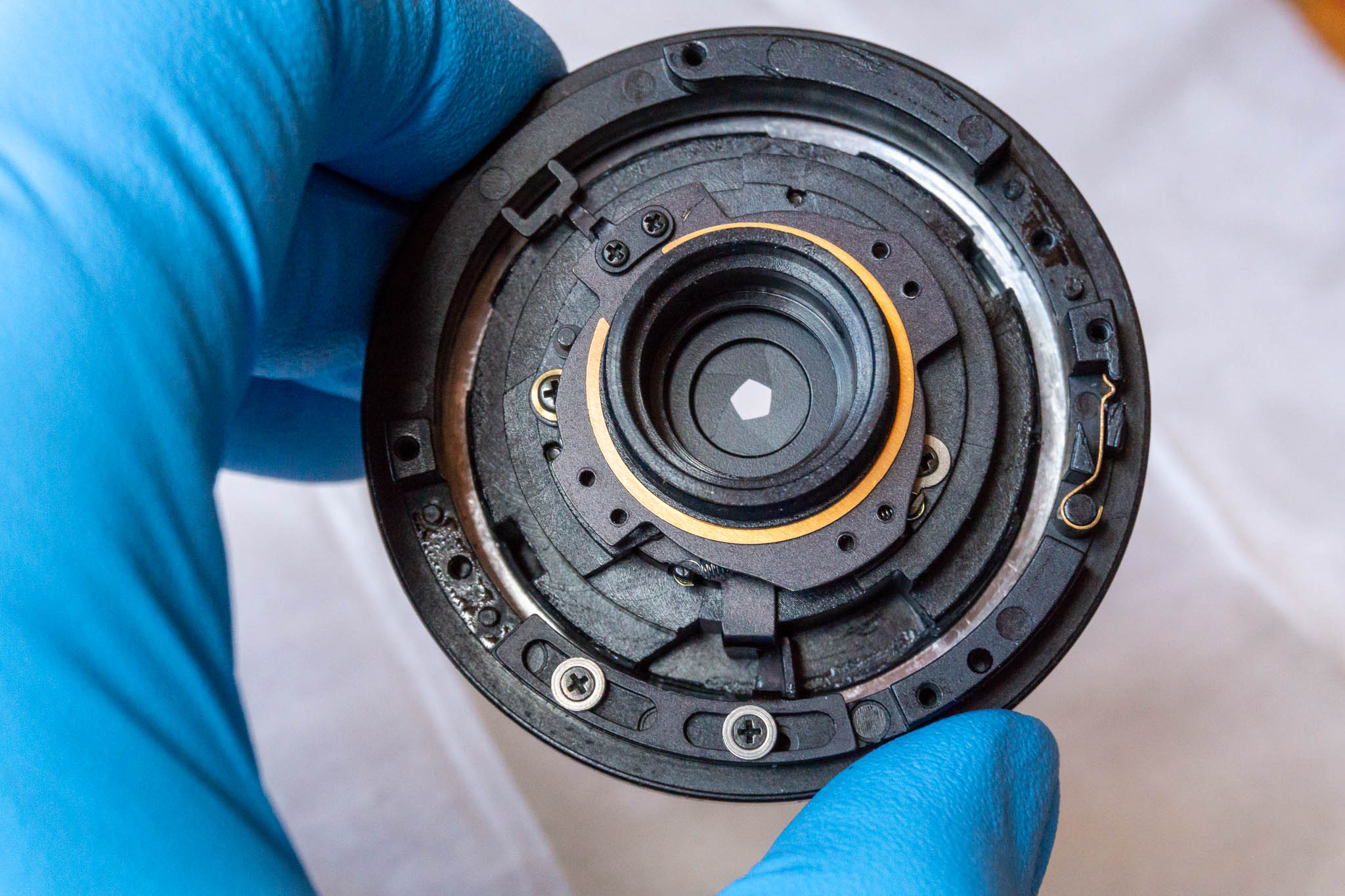
The rear of the lens before removing the aperture ring. The detent mechanism — a spring holding a ball bearing against the aperture ring — is at 3 o’clock. Be careful not to lose the ball bearing as you remove the aperture ring.

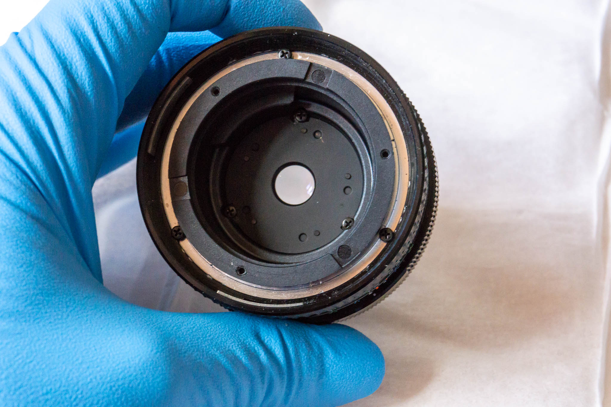
The rear of the lens after removing the aperture ring.

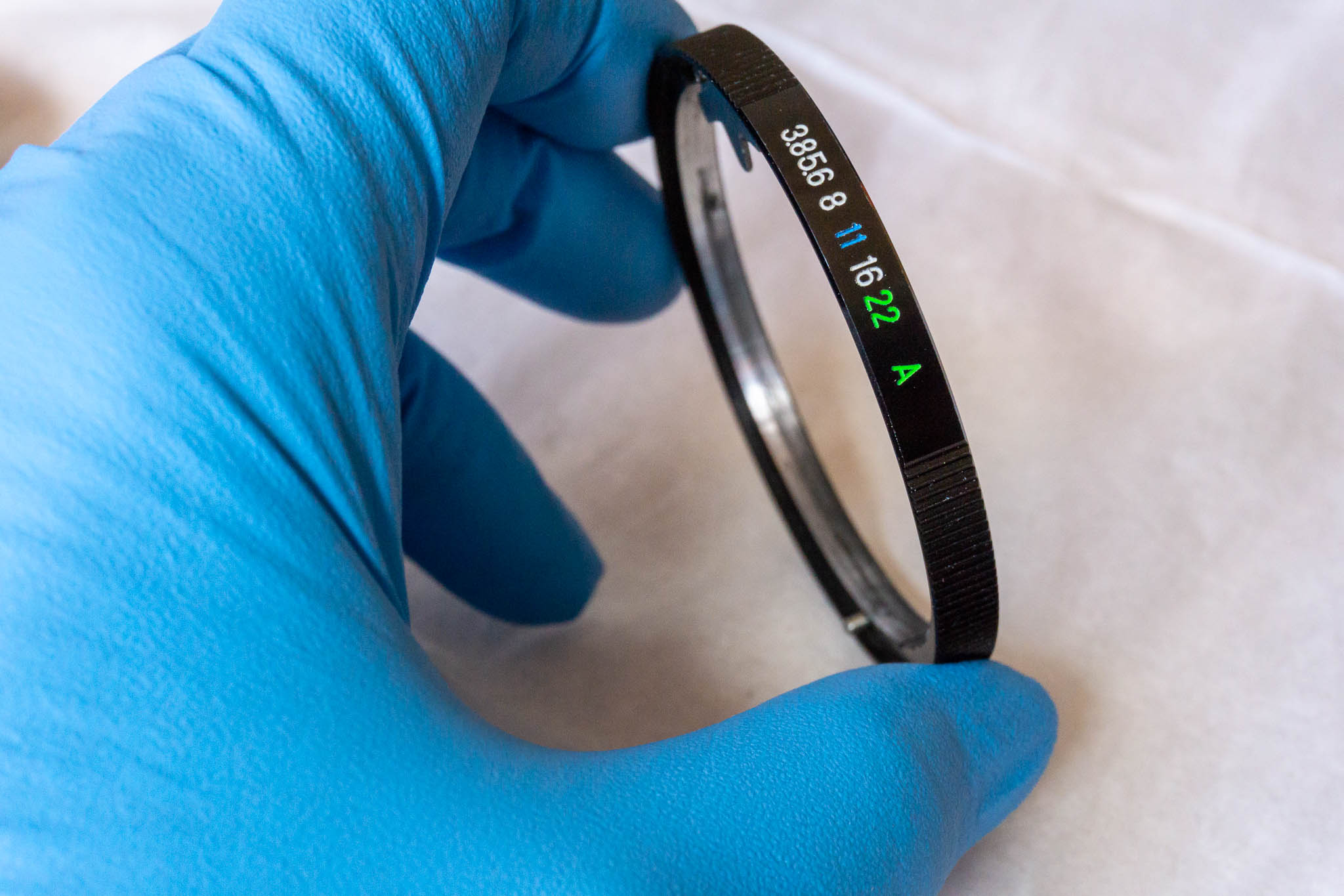
The aperture ring.

The aperture ring showing the slots for the detent mechanism (at 2 o’clock), the pin that extends the AE switch pin when “A” is selected (at 4 o´clock), and the coupling to the aperture signal lever (at 10 o’clock).
To dismantle the helical focuser, we need to be able to rotate it with respect to the main ring. This requires removing the two linear guides, the sliding automatic aperture lever coupling, and the aperture signal lever coupling.
Each linear guide is fastened by a single screw.
The automatic aperture lever coupling is fastened by two screws with washers and sleeves.
The aperture signal lever coupling is fastened by two screws. It can be attached to any one of four tabs on the aperture mechanism. I recommend making a small scratch on the correct tab before removing the coupling, so that you can reattach it to the correct tab.

The rear of the lens showing the linear guides (at 2 o’clock and 8 o’clock), the automatic aperture lever coupling (at 7 o’clock), and the aperture signal lever coupling (at 11 o’clock).

The rear of the lens after removing the linear guides.

One of the linear guides.

The rear of the lens after removing the linear guides and the automatic aperture lever coupling.

The automatic aperture lever coupling.

The rear of the lens after removing the linear guides, the automatic aperture lever coupling, and the aperture signal lever coupling.
The aperture signal lever coupling.
You can now disassemble the focus mechanism, unscrewing the focusing collar from the main ring and then the main barrel from the focusing collar.
You’re likely to get grease on your gloves at this stage, so make sure you change them before handling optics again.

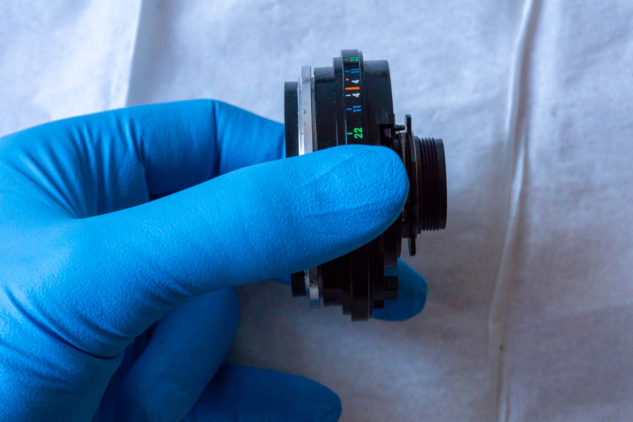
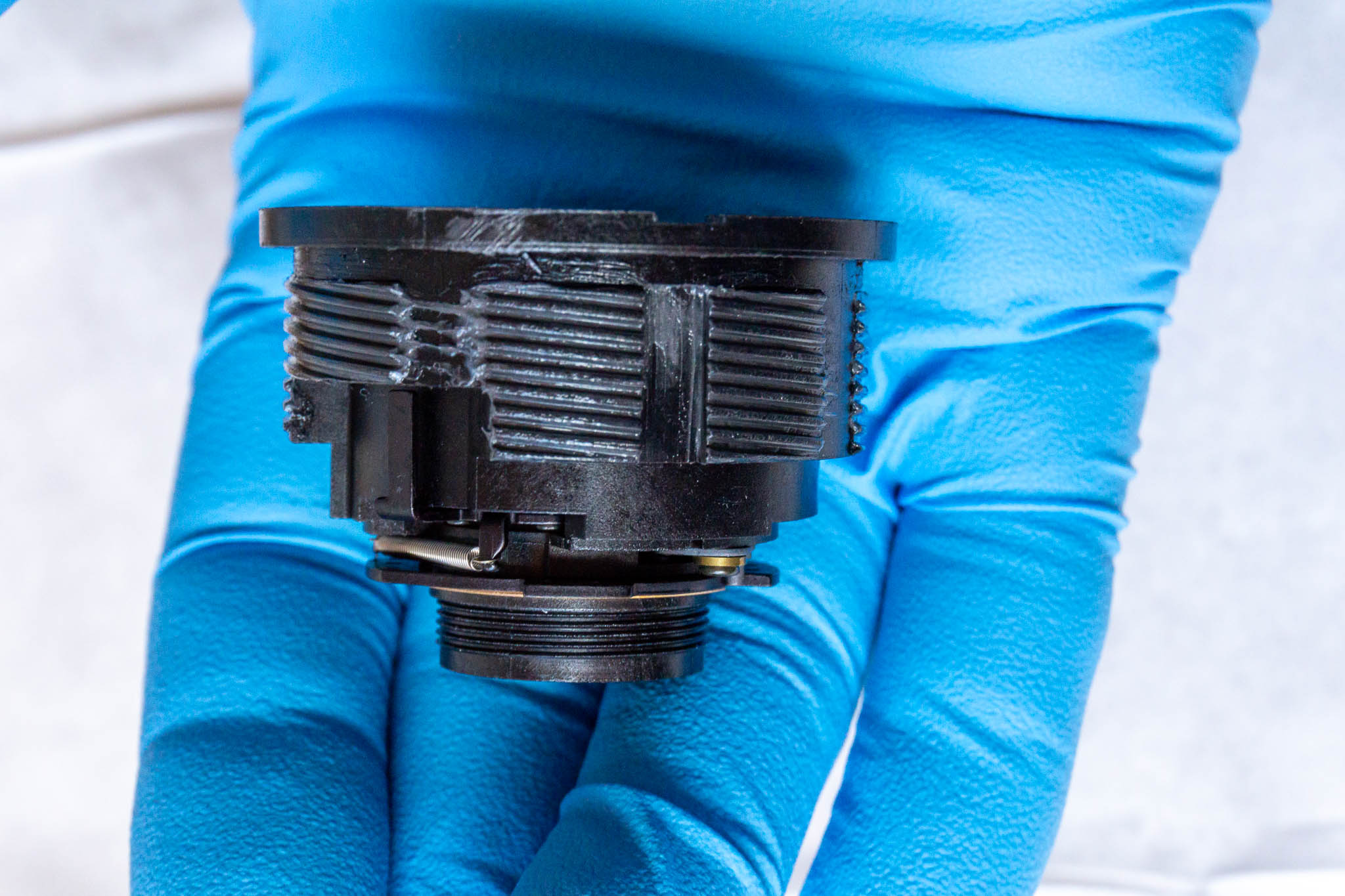
The main ring, focusing collar, and main barrel before disassembly.

The focusing collar and main barrel after removing the main ring.

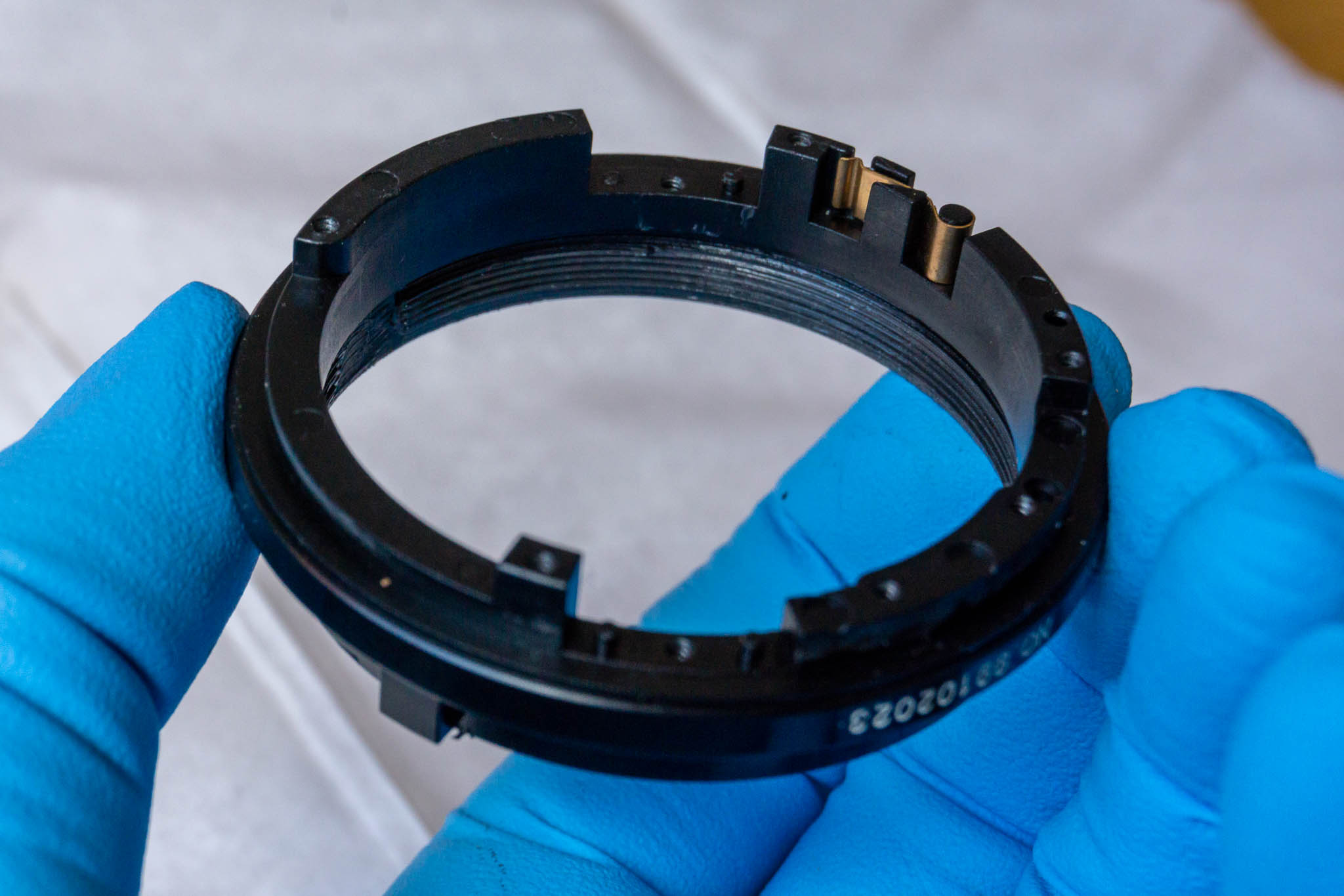
The main ring.

The main ring.

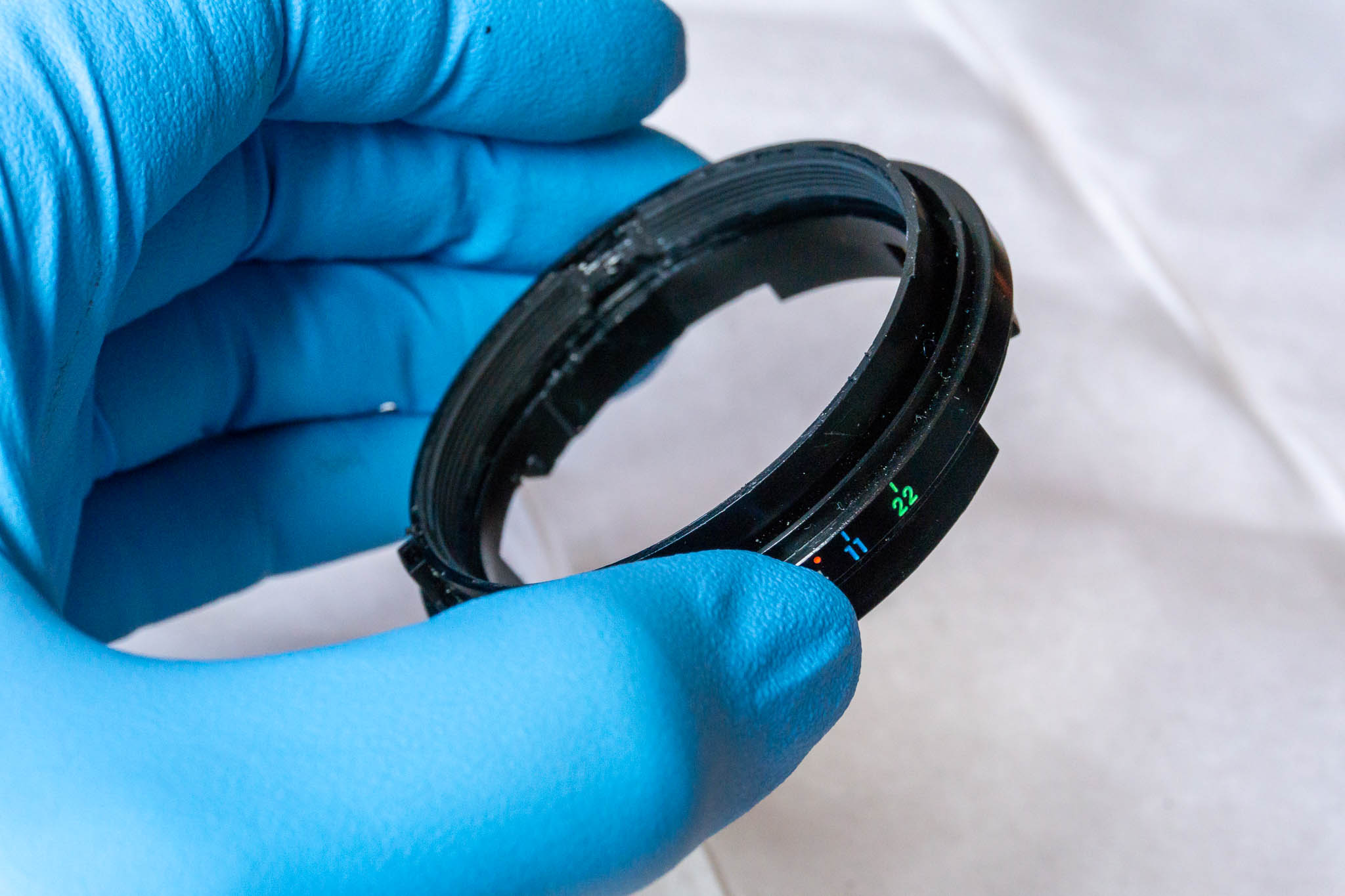
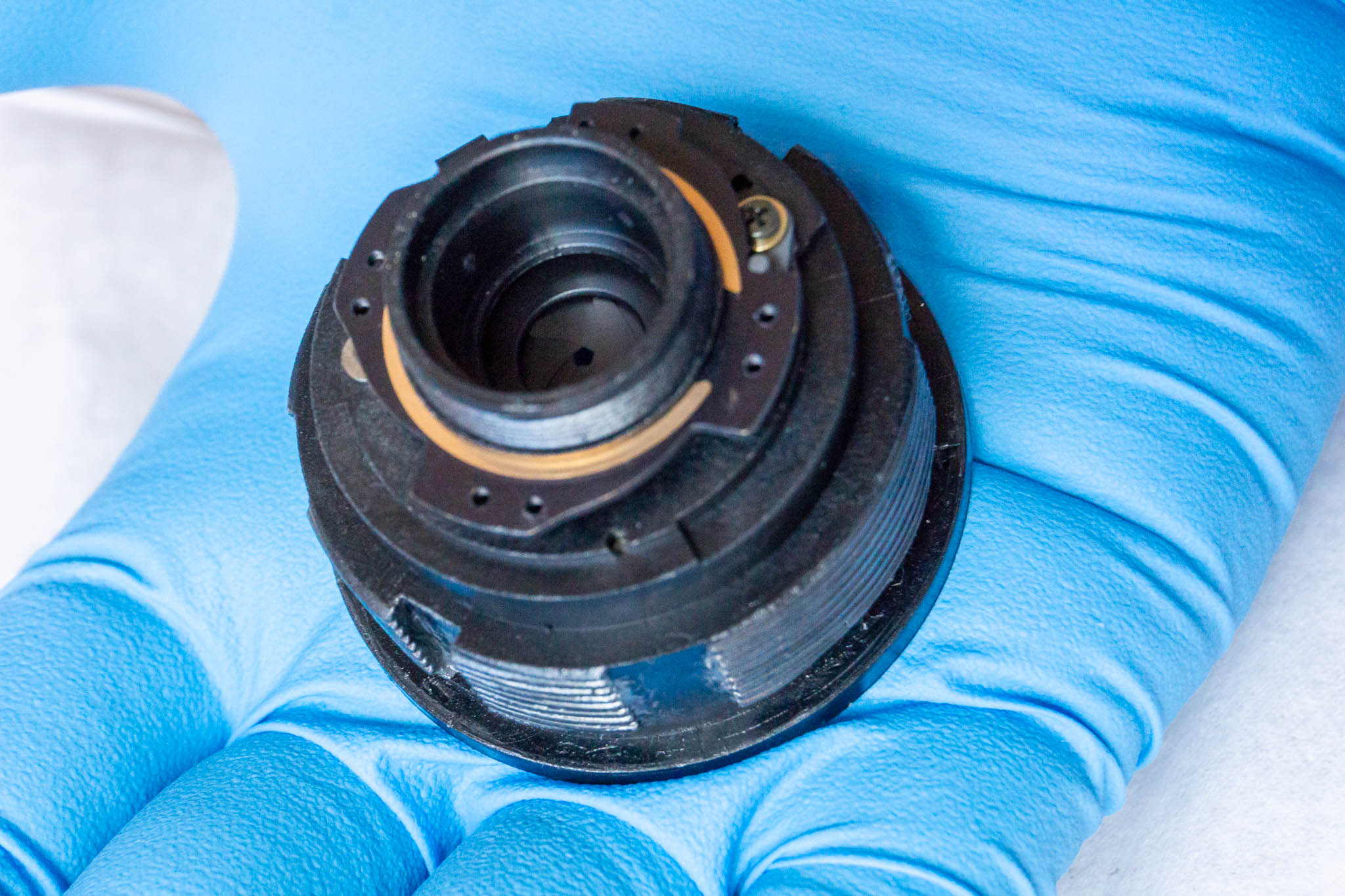
The focusing collar. Note the fine screw pitch on the outside and the coarse screw pitch on the inside.

The main barrel.

The main barrel.

The main barrel.


Reassembly
Reassembly proceeds more or less in reverse to disassembly, but there are some tricks.
I recommend doing a complete mechanical assembly (including both the focus mechanism, aperture mechanism, and mount assembly), and only then installing the front and rear optics
You need to leave clearance between the focusing collar and the main ring, otherwise the screws that attach the focusing ring to the focusing collar will touch the main ring.

Leave some clearance between the focusing collar and the main ring.
Mount the aperture ring without the ball bearing, and then use a small flat-bladed screwdriver to push back the spring enough to insert the ball bearing.
I think the trickiest part of reassembly is mating the mount assembly to the lens assembly. Here’s a description of the process. I don’t have any photos, because I only have two hands …
Hold the lens assembly in one hand with the front of the lens facing down. During the whole process, maintain the aperture ring firmly in position. If it slips, the ball bearing can be ejected by the spring and be lost. Set the aperture ring to f/3.8 and move the aperture selection lever coupling in the lens body to the corresponding position.
Hold the mount assembly your other hand with the rear of the assembly facing up. Use a finger to hold the automatic aperture lever fully CCW (when seen from above) against its spring.
Align the aperture selection lever coupling on the mount assembly and the lens assembly, mate the mount assembly to the lense assembly. Rotate the mount assembly so that the red dot on the mount assembly aligns with the red line on the lens assembly.
Insert the four screws.
After reassembly, it’s likely that you’ll need to adjust infinity focus. Coarse adjustment can be achieved by losening the three screw that attach the focusing ring to the focusing collar. Fine adjustment, if necessary, can presumably be achieved using the adjustable hard stops, but I’ve not confirmed this.

Acknowledgements
Thanks to the members of the DPReview Adapted Lens Talk Forum, especially member Lightshow, for their encouragement.
© 2018 Alan WF